Hydro Power…
Tachyon Air Powered Pump (TAPP)
A standard airlift pump is a device that pumps a liquid or slurry using only gas injection. The Tachyon Air Powered Pump (TAPP) uses water as the liquid, and the injected gas is air.
Airlift pumps operate in a two-phase flow, meaning that the flow consists of simultaneous flow of substances of two different phases. Airlift pumps have characteristics that make them more desirable than mechanical pumps in specific applications.
A recent (2007) variant called the “geyser pump” can pump with greater suction and less air. It also pumps proportionally to the air flow, permitting use in processes that require varying controlled flows. It arranges to store up the air and release it in larger bubbles that seal to the lift pipe, raising slugs of fluid.
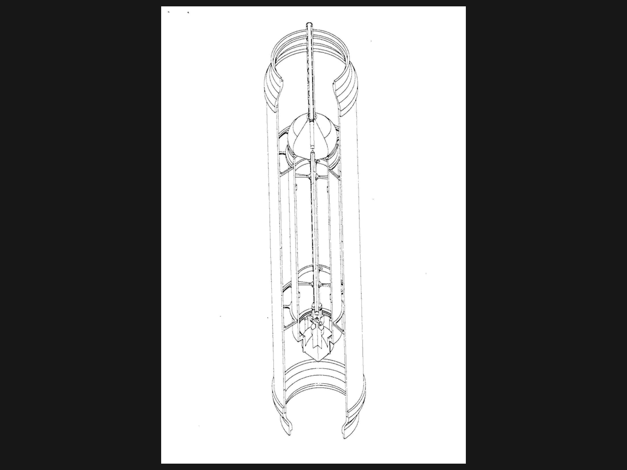
The Tachyon Air Powered Pump is a proprietary hybrid design of the airlift and geyser pumps and has only one moving part to create a big bubble slug with outer cavitation vortex. There is minimal wear, reducing the need for maintenance, and the required input energy is minimal. The pump is highly efficient when moving large volumes of water.
The lack of rotational impeller blades allows the pumps to be used for dredging applications, such as removing sediment from a riverbed or a harbor, retrofitting into existing wells, and potentially for mining valuable minerals from the ocean floor. In addition, airlift pumps can be used to transport corrosive, abrasive liquids that could also damage a mechanical pump and petroleum. Standard airlift pumps will typically operate at efficiencies ranging from 35% to 55% (Clark and Dabolt, 1986). It is Tachyon Aerospace’s belief that the TAPP will far exceed these results, establishing itself as the most efficient pump currently available.
Low efficiencies associated with existing pumps result from the high slip ratio between the air and the water, resulting in a poor transfer of momentum from the gas to the liquid. The shear and buoyant forces of the injected air acting on the water tend to pull the water up the riser, or entrain the water. The TAPP riser is oriented perfectly vertical, to maximize the buoyant force generated by the air.
In a standard pumping configuration, the air is fed from a small compressor into three air lines. Line one fills body of the pump chamber, whist the other two lines pressurize the control lines to operate the solenoid air actor block. This vale remains under constant pressure and opens and shuts the head of the pump to create the “Big Bubble Slug.” When the valve opens on the head of the pump, the vacuum effect created from the bubble leaving the pump chamber creates a vortex as the remaining water is pulled from the base chamber of the pipe over the outer fins of the pump. This vortex increases the laminar flow along the sides of the pipe, further increasing its efficiency.
During standard two-phase flow airlift operation, four different flow patterns are commonly observed. The maximum efficiency and the maximum capacity of the pump are affected by these flow patterns, which in turn result from the combination of other factors including the submergence ratio and the major and minor losses in the piping system. Minor losses are caused by the geometry and setup of the pump, including elbows in the piping, contractions, expansions in the piping, and entrances/exits of flows. Major losses result from pipe wall friction. The TAPP overcomes the pipe wall friction as described earlier by creating a cavitation vortex from its outer fins.
Using small air flow rates, the TAPP system operates to create a big-bubble/slug flow regime. As the flow rate of the air increases, the bubble drives a “slug” of water up the pipe in the slug flow regime. As the airflow continues to increase, the large air bubbles normally become unstable, resulting in the “churn flow.” However, The TAPP operates at the highest efficiency and maximum capacity near the maximum slug flow to churn flow ratios during airlift operation. The air is fed into the system form an air compressor with an 8-gallon tank that provides air delivery: 4.5 CFM @ 90 PSI, 5.5 CFM @ 40 PSI pump development road-map. The existing pump will be demonstrated in Florida at the Wimauma test site, in a closed loop configuration. The pipe loop will consist of a clear 8” up-pipe into a 8”–6” converter with bends into a 6” pipe.
As previously discussed, there are many applications and markets for the TAPP, for both enterprises and charity organizations who have invested in manual pumps that may no longer work in 3rd world countries. It is then intended that the same configuration of pipe and Tachyon pump will have an additional element added (the X-Flow Turbine) that will make this demonstration rig into a fully functional closed-loop hydro power system.
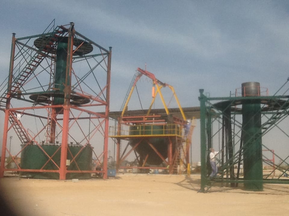
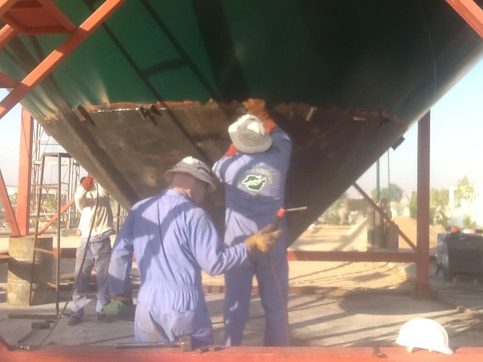
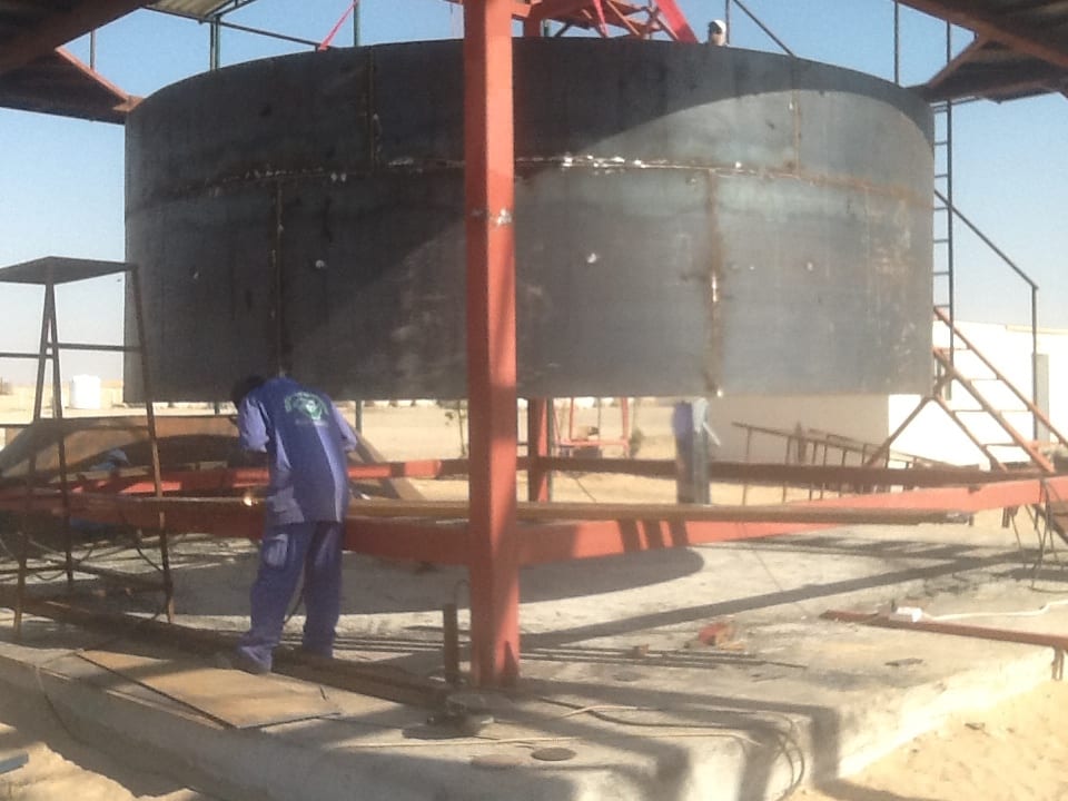
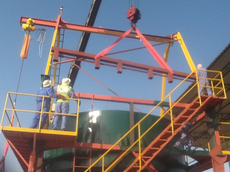
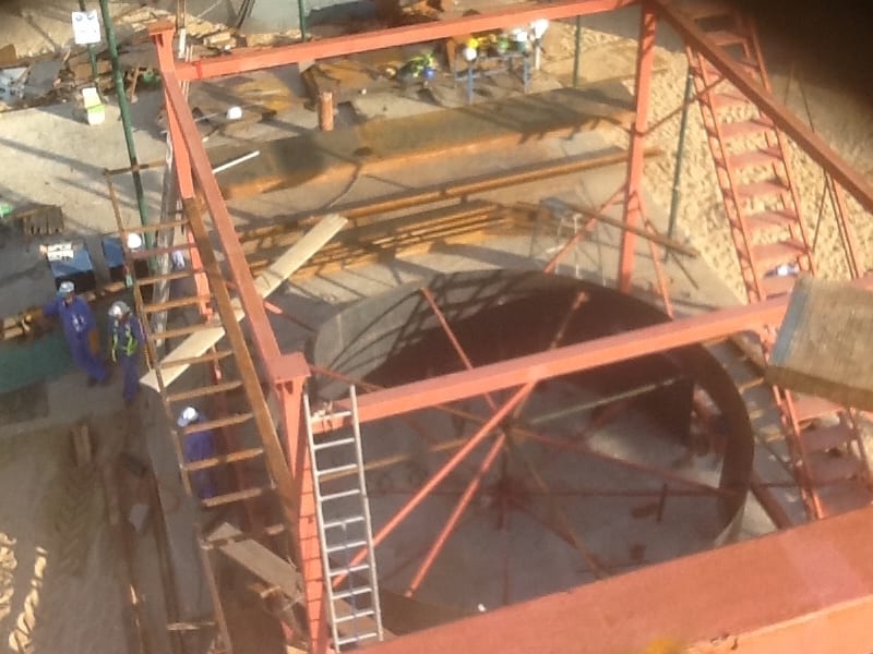
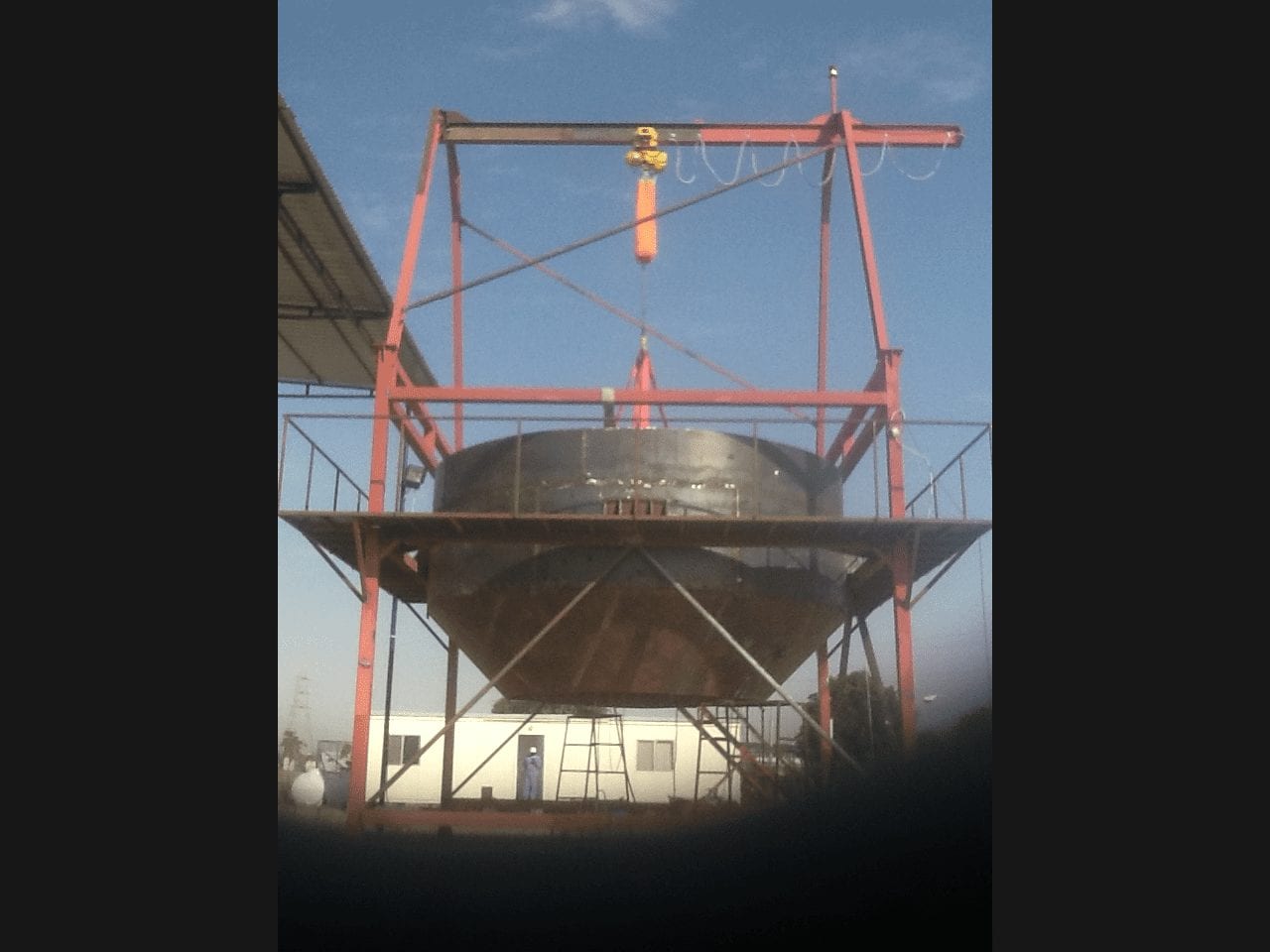
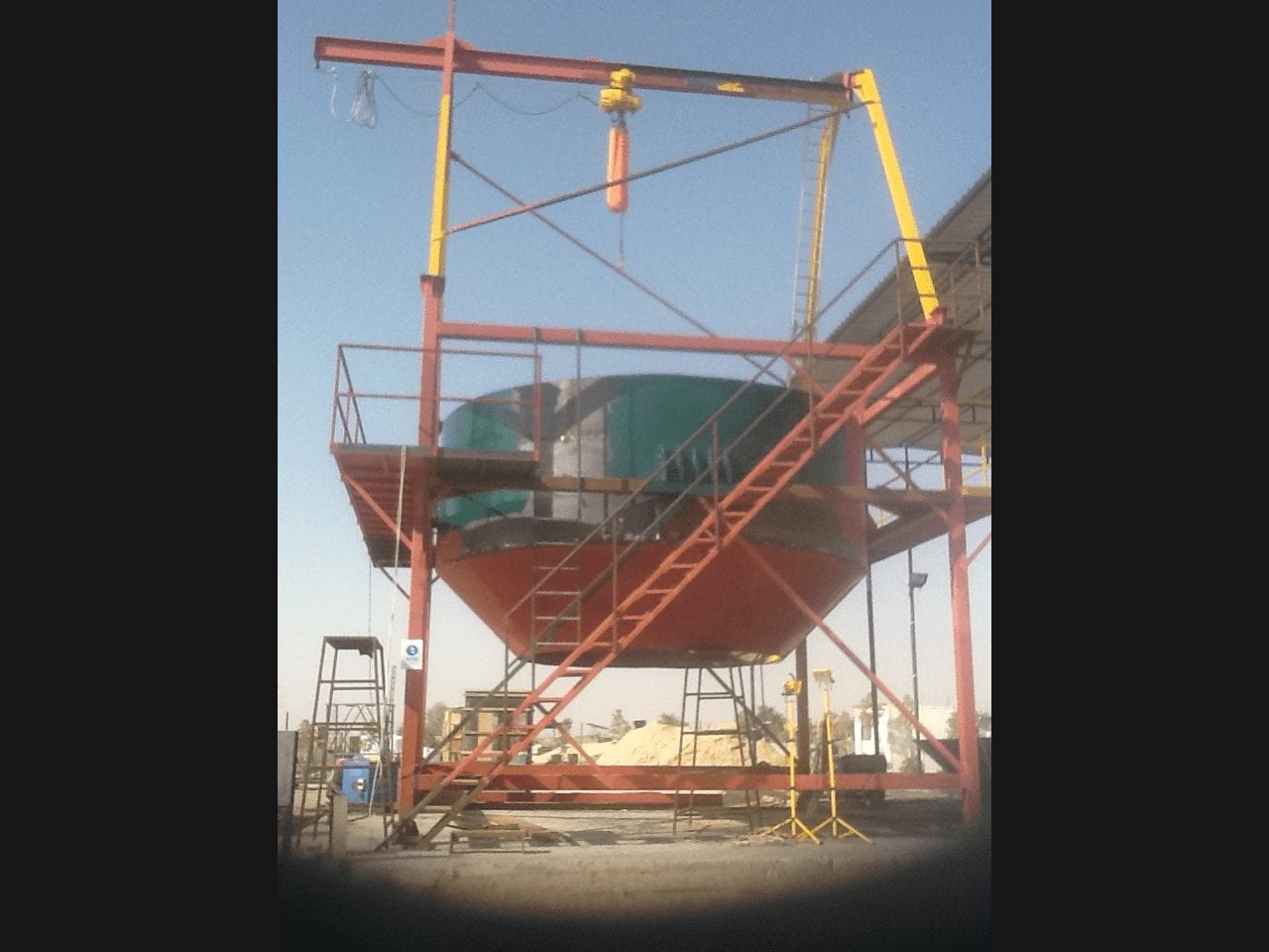
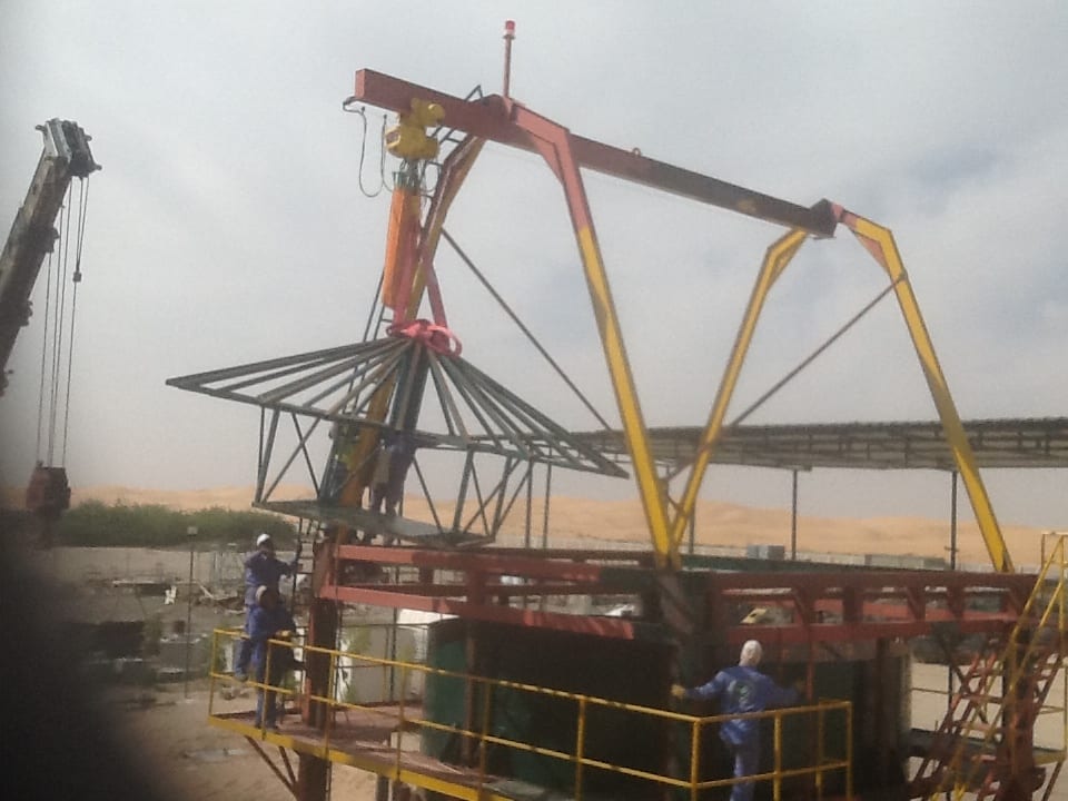
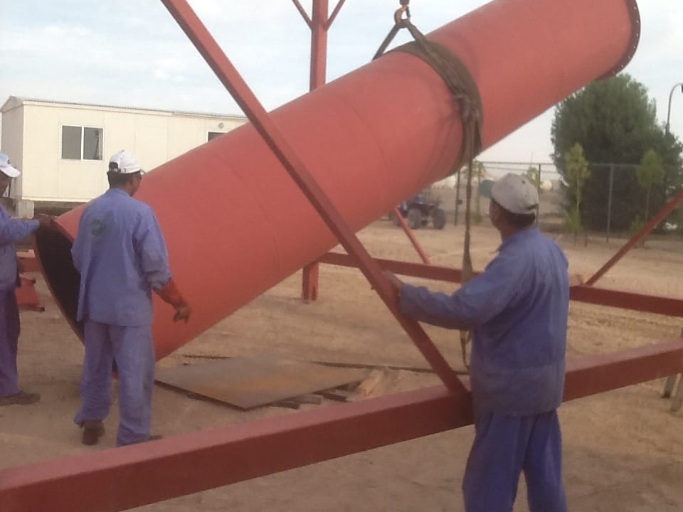
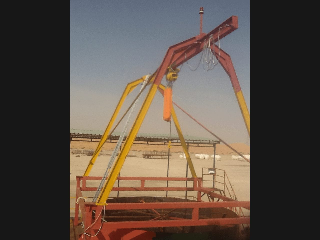
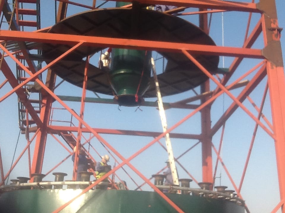
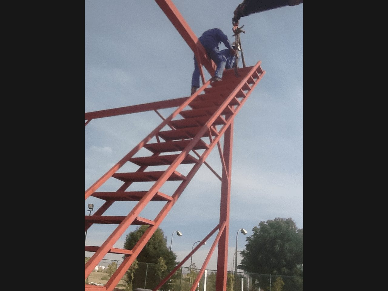
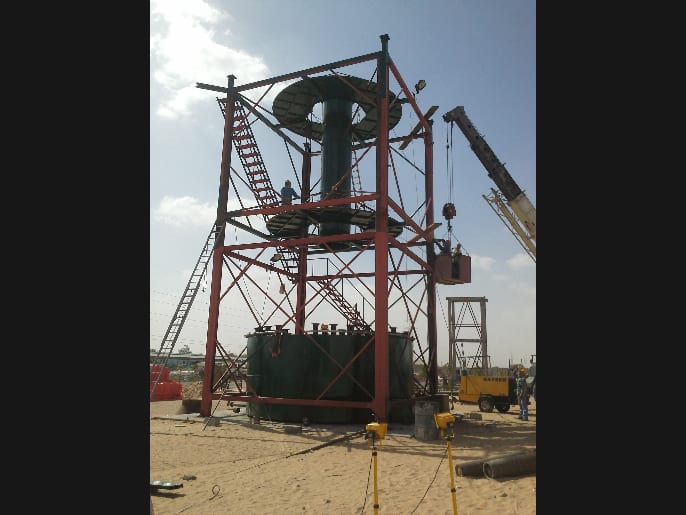
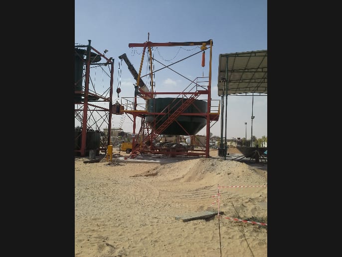
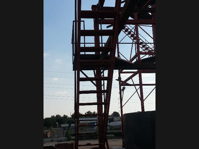
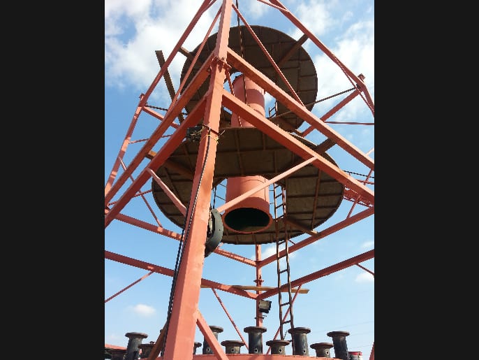
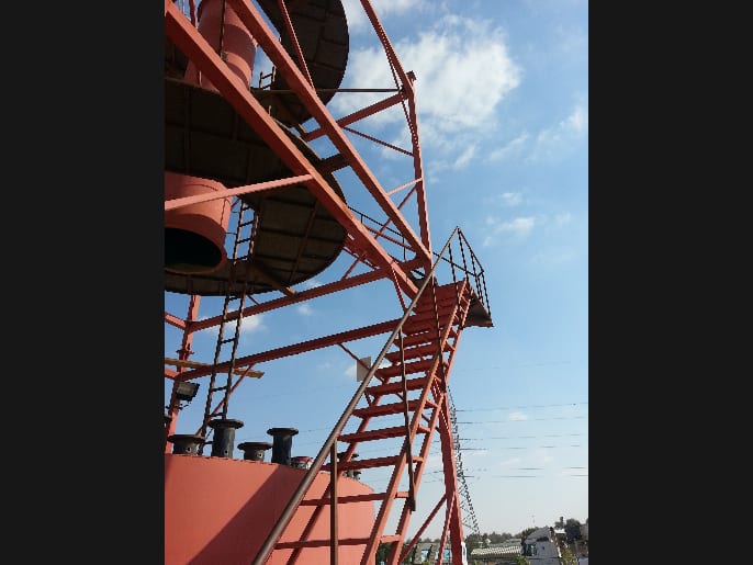
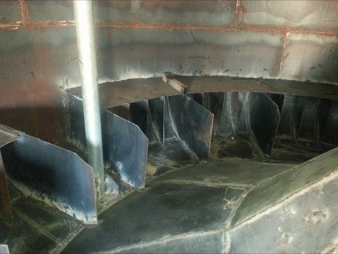
TAPP Photo Gallery